

FAQ (Q&A)
1.STructural Earthquake Response Analysis 3D: STERA_3D
FAQ (Q&A)
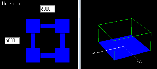
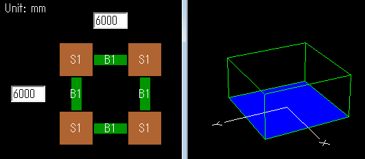
| Q01 | What is the support condition at the basement of the building? |
If nothing is entered in the basement floor (BF), the support is fixed.
You can insert a footing beam (B1) and a base spring (S1). The base spring (S1) is initially pin-supported, but you can also click the icon |
Go to top of page
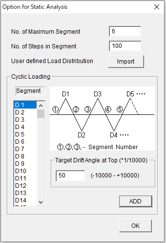
| Q02 | Can I change the target deformation angle for static analysis? |
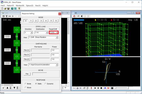
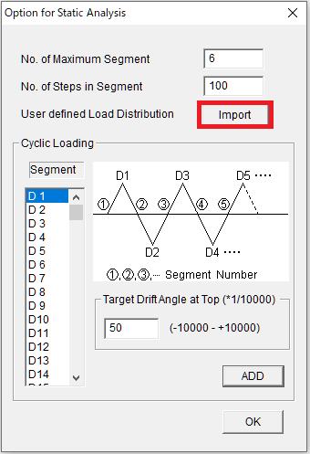
Please select [Option] > [Analysis] > [Static] from the menu. Suppose you want to apply the static force in cyclic way as shown below.
You set the target drift angle at the top of the building in each loading segment. In this case, there are 6 segments. If there is one segment. It is equal to the static push-over analysis. Please input the number of calculation steps in each segment. In this case, it is set as 100.
In the 3D view window, when you conduct static analysis, please select “Cyclic” in the pull down menu of Target Drift.
|
Go to top of page
| Q03 | Can I use change the load distribution for static analysis? |
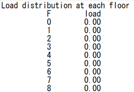
Conduct the initial analysis,
Then, you will have the “load_distribution.txt” in the folder "input".
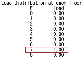
Change the values to be the original load distribution. For example, if you want to apply the point force at the top floor (7F), please change the values as follows and save the file with the new name.
Next, select [Option] > [Analysis] > [Static] from the menu, and at "User diefined Load Distribution", click [import] to import the load distibution file you created.
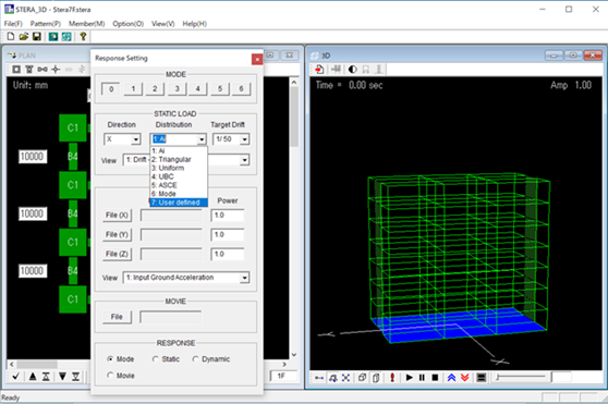
In the 3D view window, when you conduct static analysis, please select “7 User defined” in the pull down menu of Distribution.
|
Go to top of page
| Q04 | Can I change the weight distribution on the floor? |
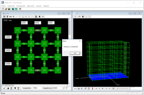
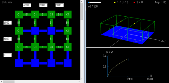
In the default setting, the floor weight is distributed automatically at each node. For example, in the following frame, although there is no column in the middle part, the beam will deform by the weight of the node and the yield hinges (yellow mark) appear in 3D view.
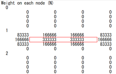
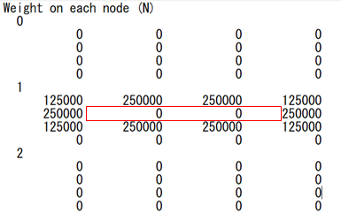
To avoid this situation, you can change the weight distibution on the floor as follows. When you conduct the initial analysis, you will have the “weight_distribution.txt” in the "input" folder.
The portion surrounded by the red line is the weight of the node at the middle column position. Change these values to zero, and distribute the weight to other nodes and save the file with the new name.
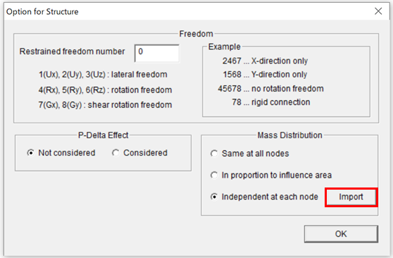
Next, select [Option] > [Structure] from the menu, and at "Mass Distribution", choose "Independent at each node" and click [import] to import the weight distribution file you created.
|
Go to top of page
| Q05 | Building is too large and program doesn't work. What can I do? |
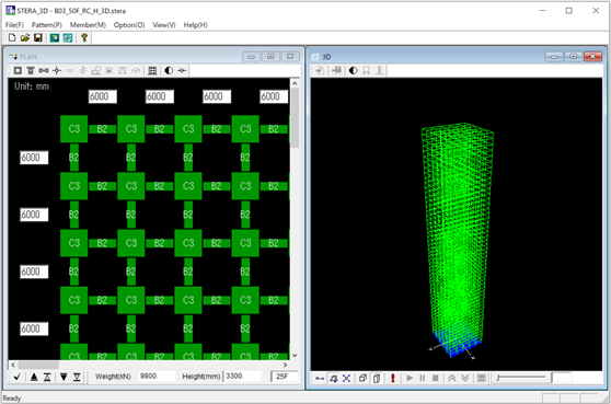
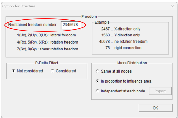
As an example, we select 50-story reinforced concrete moment resisting frame: B03_50F_RC_H_3D.stera from the sample buildings. Actually, this building has too many degrees of freedom and the program will stop automatically without any calculation. Therefore, we try to reduce the degrees of freedom as follows:
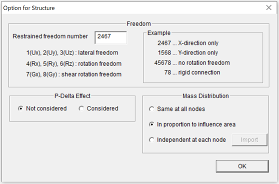
First, select [Option] > [Structure] from the menu, and put "Restrained freedom number" as "2467" which means that analysis is carried out in X-direction only, and other freedoms such as 2(Y-direction lateral freedom), 4(rotaional freedom around X-axis), 6(rotational freedom around Z-axis) and 7(shear deformation freedom around X-axis) are restrained.
Now, please make sure that the program works. |
Go to top of page
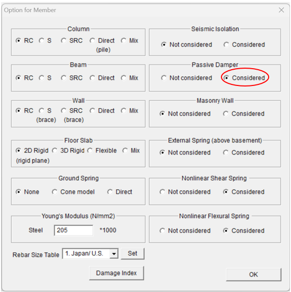
| Q06 | Can I assign both beams and walls to one member? It seems that only one of them can be assigned. |
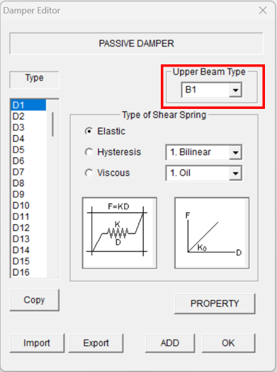
If you set the RC wall, the beam is automatically assumed to be a rigid beam. However, if you select the passive damper or the masonry wall, or the steel brace, you can set the upper beam type, as shown in the figure below (see the user manual for details).
|
Go to top of page
| Q07 | Where do I enter the Young's modulus of steel and concrete? |
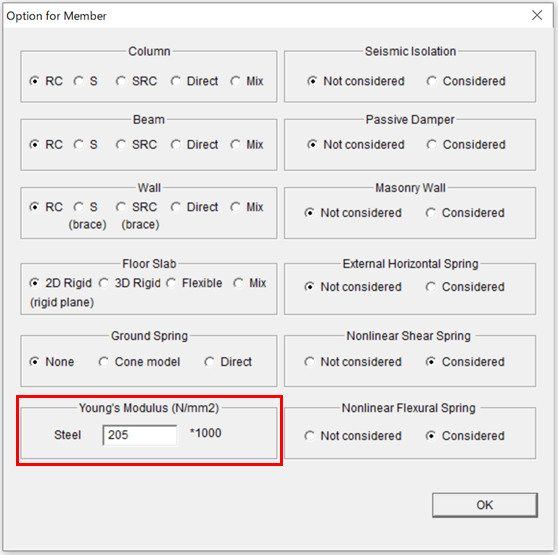
Select [Option] > [Member] from the menu. You can enter the Young's modulus of steel here (the default value is 205).
The Young's modulus of concrete is calculated from the value of concrete strength Fc by the following formula:
where, |
Go to top of page
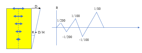
| Q08 | What is the stiffness reduction factor of reinforced concrete shear wall? |
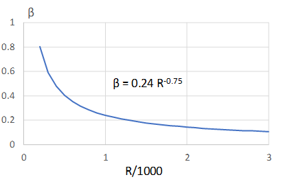
Shear cracking easily occurs in the reinforced concrete (RC) wall, and it will reduce the shear stiffness rapidly. The following graph shows the average relationship between the stiffness reduction factor β and the lateral drift angle R/1000 from the test results (referred to the “Standard for Structural Calculation of Reinforced Concrete Structure", Architectural Institute of Japan).
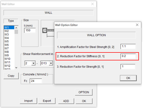
If the reduction factor is not taken into account, the RC shear wall will bear most of the seismic force. Therefore, it is reasonable to reduce the shear stiffness from the beginning in structural calculation. STERA_3D adopts β = 0.2 for the “Reduction Factor for Stiffness” in the option menu of RC wall element.
|
Go to top of page
| Q09 | What is the slab effect of reinforced concrete beam? |
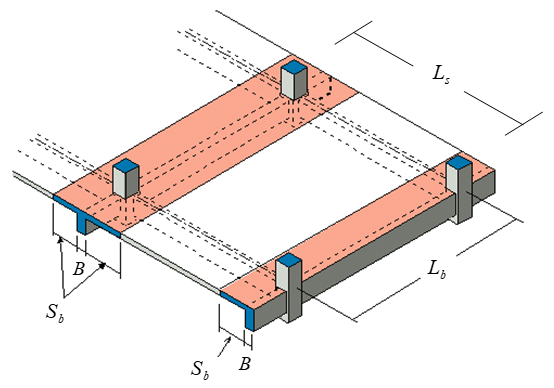
When reinforced concrete beams and floor slabs are constructed in one piece, it is known that the floor slab resists bending of the beam, and increases stiffness and yield strength. Normally, the cross section of the beam is regarded as a T shape, and a slab width of 0.1 times the beam length is considered on both sides of the beam.
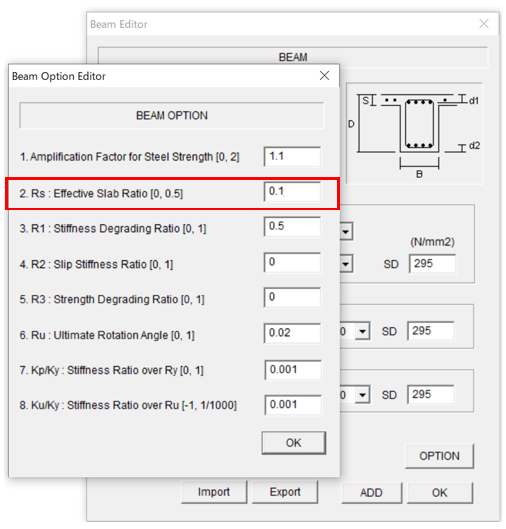
STERA_3D uses 0.1 as the initial value of slab contribution in the option menu of RC beam element.
|
Go to top of page
| Q10 | What is the slab effect of steel beam? |
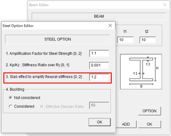
In steel buildings, steel beams and reinforced concrete floor slabs are joined with stud bolts. At this time, the bending stiffness (EI) of the steel beam is considered to increase due to the influence of the floor slab. STERA_3D uses 1.2 as the initial value of the slab effect to amplify the flexural stiffness in the option menu of steel beam element.
|
Go to top of page
| Q11 | Why is the natural period different from other programs? |
There are several possible causes. 1) Influence of stiffness reduction factor of reinforced concrete walls As described in Q08 “What is the stiffness reduction factor of reinforced concrete shear wall?”, the initial value of shear stiffness of the wall is obtained multiplying the elastic stiffness by the stiffness reduction factor (initial value 0.2). Therefore, if other programs use elastic stiffness, try setting the stiffness reduction factor to 1.0 on the option menu of wall element in STERA_3D. 2) Influence of slab effect of reinforced concrete beam As described in Q09 “What is the slab effect of reinforced concrete beam?”, the initial value of the bending stiffness of the beam is a value that takes into account the contribution of slab effect (initial value 0.1) as a T-shaped section. Therefore, if other programs use the elastic stiffness of only the beam, try setting the slab effect to 0.0 in the option menu of beam element in STERA_3D. 3) Influence of slab effect of steel beam As described in Q10 "What is the slab effect of steel beam?", the initial value of the slab effect to amplify the flexural stiffness of steel beam is 1.2. Therefore, if other programs use the elastic stiffness of only the beam, try setting the slab effect to 1.0 in the option menu of beam element in STERA_3D. |
Go to top of page
| Q12 | The bar arrangement at the center and end of the reinforced concrete beam is different. Which should I enter? |
Please enter the bar arrangement at the end of the beam, not the center. Reinforced concrete beam is modeled as a line element with nonlinear bending springs at the ends, and the restoring force characteristics of bending springs are determined based on the bar arrangement at the ends. If the bar arrangement is different between the left and right material ends, enter one (or the average) of the arrangement.
|
Go to top of page
| Q13 | Can I remove the slab at the place of atrium? |
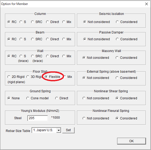
In the default setting, the floor slab is rigid for in-plane deformation (2D Rigid). To remove the slab or consider in-plane deformation of the slab, in [Option] > [Member] window, please select "Flexible" for Floor Slab.
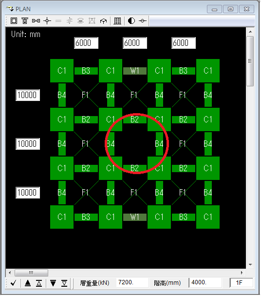
At the Plan view, please set slab member (F1, F2, ..., F100). You can remove the slab by clicking the slab member to be empty as shown by red circle in the Figure below.
|
Go to top of page
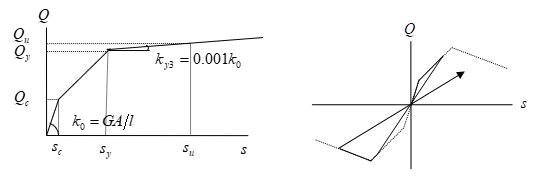
| Q14 | What is the shape of hysteresis models of reinforced concrete beams in bending and shear? |
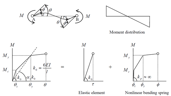
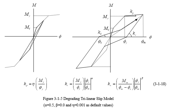
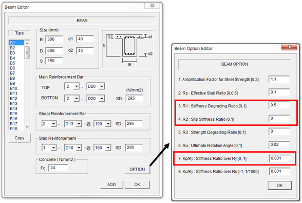
1) Hysteresis model of bending A model that takes into account the stiffness reduction due to nonliniearity and slip properties is used. The history shape after cracking is the maximum point-oriented stiffness up to yielding. After the yield point, the history shape is controlled by the following three parameters. R1: stiffness degrading ratio (return stiffness after yielding, parameter α) (default value 0.5) R2: slip stiffness ratio (parameter β) (default value 0.0) Kp/Ky: ratio of the post-yield stiffness kp to the secant stiffness ky at the yield point (parameter η) (default value 0.001) For details, please refer to the technical manual.
The values of the parameters can be changed in the option menu of the beam.
2) Hysteresis model of shears The historical geometry is origin-oriented. The post-yield stiffness should be negative, but to ensure the stability of the numerical analysis, a positive stiffness of 0.001 times the initial stiffness is given.
|
Go to top of page
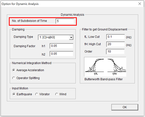
| Q15 | What is the time step for earthquake response analysis? |
The time step Δt of the acceleration data of the earthquake ground motion is subdivided for the time step for earthquake response analysis. In the "Option for Dynamic Analysis" menu by Option > Analysis > Dynamic, the initial value of the number of subdivisions is set to 5. For example, if the time step of earthquake acceleration data 0.02 seconds, the analysis time step is 0.02 / 5 = 0.004 seconds.
|
Go to top of page
| Q16 | What is the numerical integration method for earthquake response analysis? |
There is an implicit method “Average Acceleration Method (Newmark β method, β = 0.25)” and an explicit method“Operator Splitting Method”. The default setting is “Average Acceleration Method”, but when using fluid dampers or buckling hysteresis models, it automatically switches to “Operator Splitting Method”. In the case of the “Operator Splitting Method”, it is necessary to pay attention to the time step of the analysis sufficiently small in order to obtain a stable solution. |
Go to top of page
| Q17 | Is there a limit to the number of earthquake ground motion data? |
The limit on the number of data is 60000. From Version 10.5, the limit to the number of acceleration data of the earthquake ground motion does not change even if the number of subdivisions (explained in Q15) is increased. |
Go to top of page
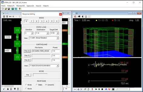
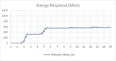
| Q18 | How can I evaluated the energy dissipated by a damper? |
For example, if you analyze the sample building "B01_04F_SC_H" (4-story steel frame with hysteresis damper) under "El Centro 1940_NS" wave, you will get the output file, "response_energy.txt".
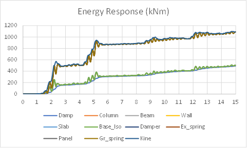
The graph shows the time history of the data in the "response_energy.txt" where the energy responses are added in the following order. Damp : dissipated energy by viscous damping
In other word, the energy response of the passive damper is the value by subtracting "Base_Iso" from "Damper" and its graph is:
|
Go to top of page
| Q19 | How to create a multi-story lumped mass model (LMM)? |
There are three cases. In all cases, only one horizontal direction is considered, so the constraint degree of freedom number is set to "2345678" except for "1 (X direction)" in "Options" > "Structure".
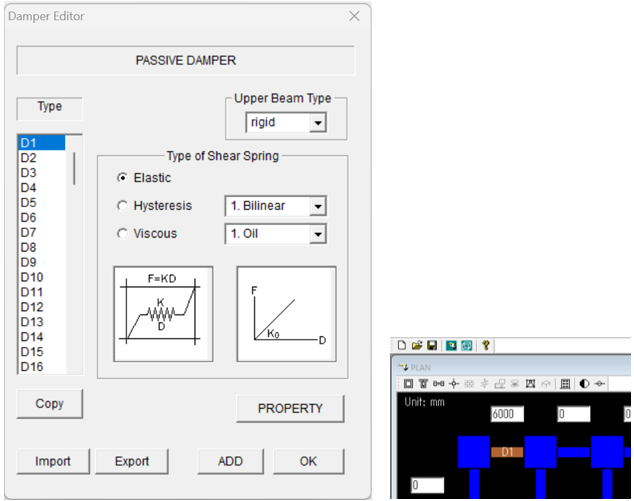
Case 1: When only the shear deformation of each layer is considered (multi-story shear-type lumped mass model) In this case, select Passive Damper (or Seismic Isolation) “Considered” in “Option” > “Member” menu.
Place one damper in each layer. The span does not affect the analysis results, so put in an appropriate value.
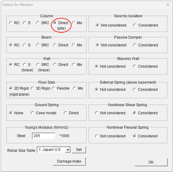
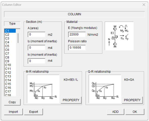
Case 2: When bending and shear deformation of each layer is considered (multi-story bending shear-type lumped mass model) In this case, select "Direct" Column (or Wall) in “Option” > “Member” menu.
Place one column in each layer. The span does not affect the analysis results, so put in an appropriate value.
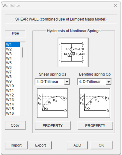
Case 3: To automatically create a multi-story lumped model from a frame model (multi-story bending shear-type lumped mass model) Use the method described in "12 Automatic generation of Lumped Mass Model (LMM)" in the User Manual. In this case, direct wall elements are automatically selected.
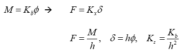
Note that the characteristics of the bending spring are the relationship between the moment M and the angle of rotation φ in each layer is replaced by the equivalent shear force F and shear deformation δ relationship. Where h is the story height.
|
Go to top of page
| Q20 | When extracting the response date, the message "Error in Shell Command" appears. |
Please put "Response.exe", "STERA_3D.exe" , and "input" folder in the same folder. |
Go to top of page
2.STructural Earthquake Response Analysis FEM: STERA_FEM